Turnstiles by www.TURNSTILES.us
Military Grade, Architectural Series Turnstiles and Matching Turnstile Gates 


Troubleshooting Guide for 6100 and 8100 Control Heads

Installation of Control Head | Common Mechanical Problems


Steps for Troubleshooting the Installation of an Electronic Control Head

1. Do not change the wiring configuration. All the control heads are tested for proper operation before shipment to customer.

2. Always test control head electronically before hooking it up to the exterior system (card reader, push button, remote, etc.).

3. One light on each timer should be on if the control head is wired properly. If it is not, make sure all wires are securely fixedin their respective terminals. This includes all wires running to and from the limit switch, timer, solenoid, and card reader (if applicable). Follow the wiring diagram. Check to see if the solenoid is grounding out on the head channel. Heavy plastic is provided to protect the terminals from grounding out on the head channel.

4. Check the power supply to the transformer that actuates the solenoid on the control head. Verify that the primary side of the transformer is being supplied 120 VAC.

5. Check the secondary voltage on the transformer. Verify that the output voltage on the secondary side of the transformer is 24 VDC.

6. Blue Timer: Provide a temporary connection between the number 5 & 6 terminals on the timer block. When contact is made the two timer lights should turn on. The solenoid should actuate when this connection is made. When the solenoid actuates one of two possible outcomes will occur. If passage through the gate is allowed upon solenoid actuation, proceed to Step 7. If the passage through the gate fails to occur, proceed to Step 8.

6B Circuit Board: Provide temporary contact between enter or exit input + and -. The solenoid should actuate when connection is made. When the solenoid actuates one one of two possible outcomes will occur. If passage through the gate is allowed upon solenoid actuation, proceed to step 7. If the passage through the gate fails, proceed to step 8.

7. The proper operation of the control head indicates that the problems being encountered are associated with the card reader (if applicable). Check the card reader for proper operation and its configuration with the control head.

8. Several things can cause the control head not to open. Make sure that neither the gate, nor the solenoid in the control head is in a bind. The control head will not always unlock if it is under pressure. Next listen to hear if the locking pawls inside the head unit are moving. Sometimes the locking pawls will get lodged in the track and the solenoid is unable to pull them free. Consult with www.TURNSTILES.us before opening the top of the control head.

9. Check to see if the control head is installed correctly - not backwards. (Only applicable in the 400 Series Models).

10. Feel free to contact www.TURNSTILES.us for additional help if the above steps fail to alleviate your problems.


top of page

Commonly Encountered Mechanical Problems

1. Correcting Clockwise or Counterclockwise Direction Problems
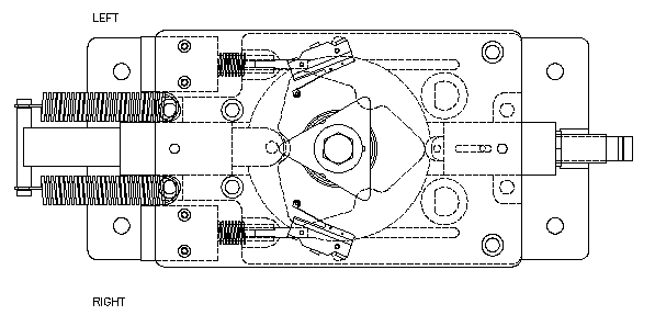
Head troubleshoot
  • Manually operated control head - One solenoid only:
    The control head will operate in a CW direction if the solenoid is located in the left side of the control head.
  • The control head will operate in a CCW direction if the solenoid is located in the right side of the control head.
  • The direction can always be verified by actuating the solenoid allowing the control head to rotate in the designated direction.
  • Electronic operated control head - Two solenoids:
    Activating the solenoid on the left side of the control head allows CCW rotation of the control head.
  • Activating the solenoid on the right side of the control head allows CW rotation of the control head.
  • To change Direction:
    First, remove the 2 screws using a 9/64 Allen Wrench.
    Take the solenoid, spring and locking pawl out of the control head.
    Transfer these parts to other side of control head.
    The control head will now operate in the opposite direction.

Note: The locking pawl is offset from the solenoid - not centered. The high side of the locking pawl should be toward the top of the control head.
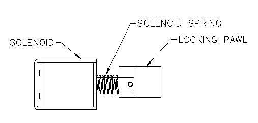
Solenoid

2. Bind in Control Head

  • Check and make sure that the turnstile arm is not under pressure
  • Sometimes the internal parts of the control head may lose alignment during shipment. The centering bar or solenoid may need to be realigned.
  • The centering bar can be realigned by tapping the centering bar to the center position and re-tightening the 5/16 set screws on top of control head with a 5/32 Allen wrench.
  • The solenoid can be realigned by loosening the 8/32 set screws with 9/64 Allen wrench and aligning the body of the solenoid parallel to the body of the control head.
  • If the cause of the binding can not be found or the control head is equipped with key locks, the entire control head needs to be sent back to the factory for repair.

3. Shock Replacement

  • Set the shock to the lowest setting with the centering bar in the locked position. Thread the shock into the housing until it stops. Back the shock out about 1 - 1 ® turns and lock it down with the lock nut. The new shock inserted needs to be adjusted by the following procedure.

4. Shock Adjustment

  • Adjust the shock tension with the centering bar in the locked position. The shock tension is adjusted with the shock set screw. Do not attempt to adjust shock tension using the lock nut to adjust shock distance in the housing. Approximate tension settings are listed below
  • Approximate Tension Settings:
    Full Height - 0
    H.G. - 3
    Waist High - 5
    (0) is the maximum shock tension setting.
    (9) is the minimum shock tension setting.

5. Trantorque Adjustment

  • The control head may have a trantorque used for breakaway purposes. Over time the arm may lose alignment and split apart. The trantorque can be loosened up using a torque wrench and a 1 ª crows foot and turning in a CCW direction. Apply Counter torque using 1 ® wrench turning and turning in a CW direction. Next reposition the bolt hole pattern of the hub parallel with the top of the unit. Retighten the trantorque to 500-inch lbs. with a torque wrench. Exceeding the recommended torque specifications may prevent the unit from slipping.

6. People Getting Locked in Turnstile

  • Make sure the rotor in positioned correctly. The security bars should positioned 60 degrees off top dead center.
  • The timer should be set to the proper time. The timer is set to 10 seconds at the factory.
  • Make sure the top cam is set in the proper position When the cam hits the limit switch the timer is shut down which releases solenoid to lock. The full motion of the turnstile must exceed 60 degrees when locking so that it can continue to turn.
  • The people may be taking too long to walk through the gate. Provide a training flyer on the operation of the turnstile to each employee. If necessary increase the timer setting up in seconds or even minutes to alleviate if the problem. Remember the level of security is lowered, as the timer is set higher.
top of page

Home  |   Turnstile FYI  |   Who We Are  |   High Security Turnstiles  |   Beacon Series  |   Executive Series  |   EntraPASS Global Edition
Brute Series  |   Railings & Gates  |   Rental Turnstile  |   Tech Docs  |   Contact Us  |   Site Map  |   Links  |   Turnstile Selection

Phone: 303.670.1099 ext 11   •   Fax: 303.679-8949   •   email: patrick.mcallister@EntraPass.com   •   Global Security Integration
8641 S. Warhawk Road * Conifer, CO 80433